Overview
Flight controller needs to set CAN interface parameters to identify external CAN module devices.
Some CAN modules have internal parameters that configure the functions of the CAN module.
Ardupilot Flight Controller
The Mission Planner PC software was used for parameter setting.
Set flight controller parameters
Connect to the flight controller and open the host computer software page(CONFIG->Full Parameter Tree).
Search for and set the following parameters and restart the flight controller after prompting for successful writing of the parameters.
Generally, flight controllers have two CAN buses, CAN1 or CAN2. Connect the CAN module device according to the corresponding CAN interface of the flight controller, and set the corresponding parameters to communicate normally with the peripheral CAN device.
//CAN1 Interface
CAN_P1_DRIVER = 1
CAN_D1_PROTOCOL = 1
//CAN2 Interface
CAN_P2_DRIVER = 1
CAN_D2_PROTOCOL = 1
Set CAN module parameters
If you do not need to modify the internal parameters of the CAN module or view the data of the CAN module, you do not need to perform the following operations.
Connect the CAN module
Connect the host computer by USB, set the following parameters, and turn on the SLCAN function to map the CAN1/CAN2 interface to a USB port.
//Maps the CAN1 interface
CAN_SLCAN_CPORT = 1
SERIAL7_PROTOCOL = 22
//Maps the CAN2 interface
CAN_SLCAN_CPORT = 2
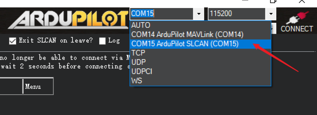
SERIAL7_PROTOCOL = 22After the flight controller is powered off and restarted, when reconnecting the host computer software, you need to select the serial port containing SLCAN characters, and you do not need to click “CONNECT” at this time.
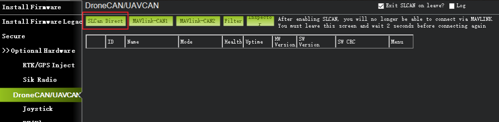
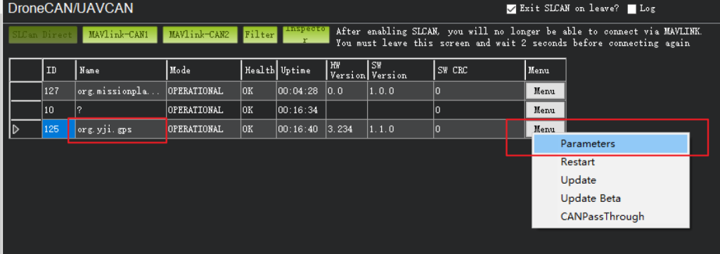
Open the host computer software page(SETUP->Optional Hardware->DroneCAN/UAVCAN),click the “SLCan Direct” button.
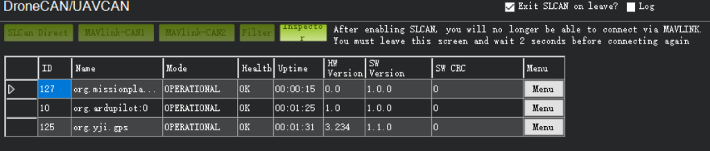
The flight controller will automatically scan the module device on the corresponding CAN bus, the scan result will present a list of devices, click the corresponding device Menu button, you can view data, view parameter, parameter modification, firmware upgrade and other operations.
Mission planner host computer software version 1.3.8 or later, you can also choose to use MAVlink to view the peripheral list of DroneCAN without setting flight control parameters.
Connect to the host computer software via USB or telemetry,open the page (SETUP->Optional Hardware->DroneCAN/UAVCAN).
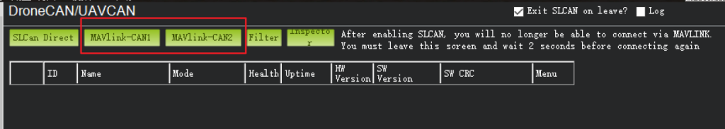
Select “MAVlink-CAN1” or “MAVlink-CAN2” to view the module devices mounted on the corresponding CAN bus.
Parameter setting
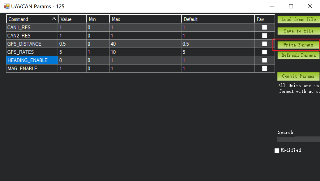
Find the corresponding CAN module device in the device list and click “Menu->Parameters”.
After opening the parameter setting window, you can set the internal parameters of the CAN module here, and after modifying the parameters, you should click “Write Params” to save the parameters.
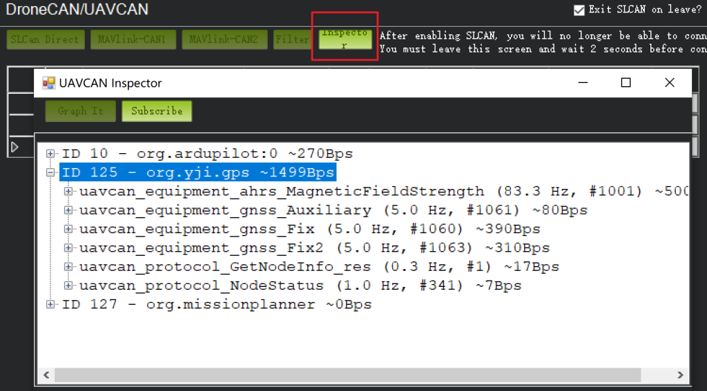
View data
Click the “Inspector” button in the page to view real-time data for each device on the CAN bus.
PX4 Flight Controller
Use QGoundControl host computer software for parameter setting.
Set flight controller parameters
Connect to the flight controller, set the following parameters and restart.
UAVCAN_ENABLE = Sensors Automatic Config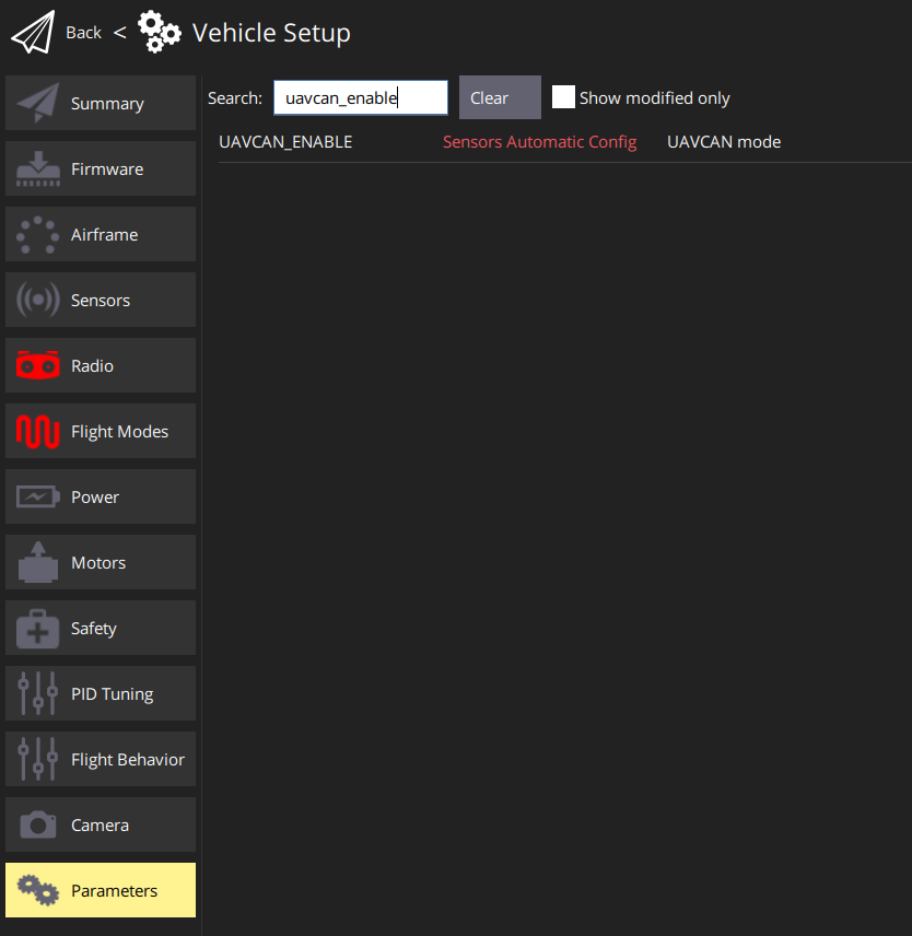
Set CAN module parameters
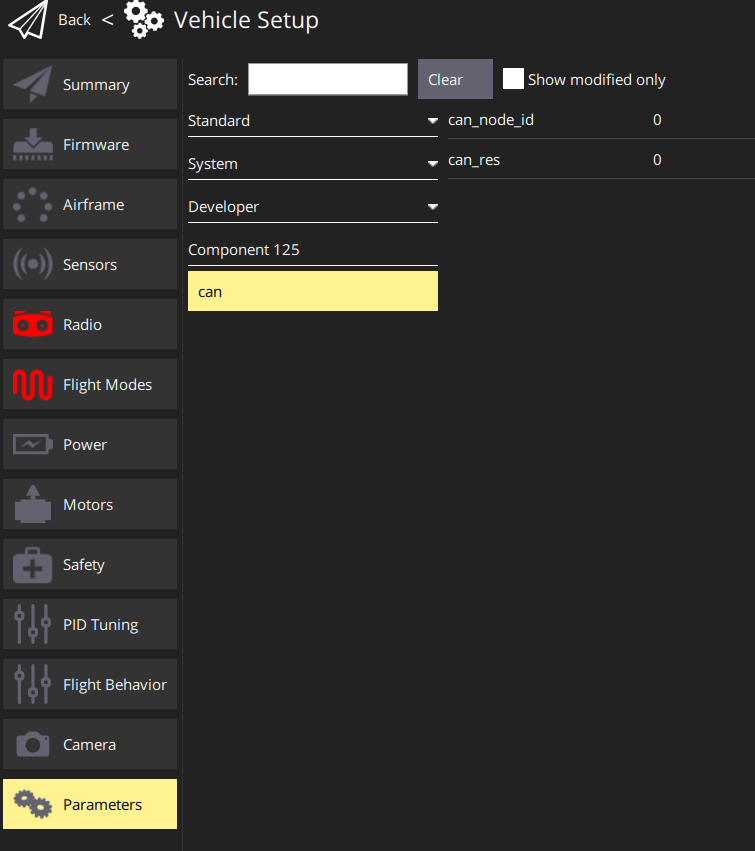
Open the host computer page(Vehicle Setup -> Parameters),swipe the page to the very bottom position and you can see the CAN device.
For example, in the figure below, the CAN device is “Component 125”, click to expand to see the parameters of the device, and then you can directly modify the parameters of the CAN device here,remember to save the parameters after modification.
Note: At present, in the PX4 firmware, the internal parameters of the CAN device can only be modified through the CAN1 interface, and this cannot be done if the CAN device is connected to the CAN2 port.